Introduction

A virtual private network, or VPN, allows you to securely encrypt traffic as it travels through untrusted networks, such as those at the coffee shop, a conference, or an airport.

IKEv2, or Internet Key Exchange v2, is a protocol that allows for direct IPSec tunneling between the server and client. In IKEv2 VPN implementations, IPSec provides encryption for the network traffic. IKEv2 is natively supported on some platforms (OS X 10.11+, iOS 9.1+, and Windows 10) with no additional applications necessary, and it handles client hiccups quite smoothly.

In this tutorial, you’ll set up an IKEv2 VPN server using StrongSwan on an Ubuntu 18.04 server and connect to it from Windows, macOS, Ubuntu, iOS, and Android clients.

Prerequisites

To complete this tutorial, you will need:

One Ubuntu 18.04 server configured by following the Ubuntu 18.04 initial server setup guide, including a sudo non-root user and a firewall.

Step 1 Installing StrongSwan

First, we’ll install StrongSwan, an open-source IPSec daemon which we’ll configure as our VPN server. We’ll also install the public key infrastructure component so that we can create a certificate authority to provide credentials for our infrastructure.

Update the local package cache and install the software by typing:

$ sudo apt update
$ sudo apt install strongswan strongswan-pki ufw

Now that everything’s installed, let’s move on to creating our certificates.

Step 2 Creating a Certificate Authority

An IKEv2 server requires a certificate to identify itself to clients. To help us create the certificate required, the strongswan-pki package comes with a utility to generate a certificate authority and server certificates. To begin, let’s create a few directories to store all the assets we’ll be working on. The directory structure matches some of the directories in /etc/ipsec.d, where we will eventually move all of the items we create. We’ll lock down the permissions so that our private files can’t be seen by other users:

$ mkdir -p ~/pki/{cacerts,certs,private}
$ chmod 700 ~/pki

Now that we have a directory structure to store everything, we can generate a root key. This will be a 4096-bit RSA key that will be used to sign our root certificate authority.

Execute these commands to generate the key:

ipsec pki --gen --type rsa --size 4096 --outform pem \
> ~/pki/private/ca-key.pem

Now that we have a key, we can move on to creating our root certificate authority, using the key to sign the root certificate:

$ ipsec pki --self --ca --lifetime 3650 --in ~/pki/private/ca-key.pem \
    --type rsa --dn "CN=VPN root CA" --outform pem > ~/pki/cacerts/ca-cert.pem

You can change the distinguished name (DN) values to something else to if you would like. The common name here is just the indicator, so it doesn’t have to match anything in your infrastructure.

Now that we’ve got our root certificate authority up and running, we can create a certificate that the VPN server will use.

Step 3 Generating a Certificate for the VPN Server

We’ll now create a certificate and key for the VPN server. This certificate will allow the client to verify the server’s authenticity using the CA certificate we just generated.

First, create a private key for the VPN server with the following command:

$ ipsec pki --gen --type rsa --size 4096 --outform pem > ~/pki/private/server-key.pem

Now, create and sign the VPN server certificate with the certificate authority’s key you created in the previous step. Execute the following command, but change the Common Name (CN) and the Subject Alternate Name (SAN) field to your VPN server’s DNS name or IP address:

$ ipsec pki --pub --in ~/pki/private/server-key.pem --type rsa \
    | ipsec pki --issue --lifetime 1825 \
        --cacert ~/pki/cacerts/ca-cert.pem \
        --cakey ~/pki/private/ca-key.pem \
        --dn "CN=server_domain_or_IP" --san "server_domain_or_IP" \
        --flag serverAuth --flag ikeIntermediate --outform pem \
    >  ~/pki/certs/server-cert.pem

Now that we’ve generated all of the TLS/SSL files StrongSwan needs, we can move the files into place in the /etc/ipsec.d directory by typing:

$ sudo cp -r ~/pki/* /etc/ipsec.d/

In this step, we’ve created a certificate pair that would be used to secure communications between the client and the server. We’ve also signed the certificates with the CA key, so the client will be able to verify the authenticity of the VPN server using the CA certificate. Now that have all of the certificates ready, we’ll move on to configuring the software.

Step 4 Configuring StrongSwan

StrongSwan has a default configuration file with some examples, but we will have to do most of the configuration ourselves. Let’s back up the file for reference before starting from scratch:

$ sudo mv /etc/ipsec.conf{,.original}

Create and open a new blank configuration file by typing:

sudo vim /etc/ipsec.conf

First, we’ll tell StrongSwan to log daemon statuses for debugging and allow duplicate connections. Add these lines to the file:

config setup
    charondebug="ike 1, knl 1, cfg 0"
    uniqueids=no

conn ikev2-vpn
    auto=add
    compress=no
    type=tunnel
    keyexchange=ikev2
    fragmentation=yes
    forceencaps=yes
    dpdaction=clear
    dpddelay=300s
    rekey=no
    left=%any
    leftid=@server_domain_or_IP
    leftcert=server-cert.pem
    leftsendcert=always
    leftsubnet=0.0.0.0/0
    right=%any
    rightid=%any
    rightauth=eap-mschapv2
    rightsourceip=10.10.10.0/24
    rightdns=8.8.8.8,8.8.4.4
    rightsendcert=never
    eap_identity=%identity

Save and close the file once you’ve verified that you’ve configured things as shown.

Now that we’ve configured the VPN parameters, let’s move on to creating an account so our users can connect to the server.

Step 5 Configuring VPN Authentication

Our VPN server is now configured to accept client connections, but we don’t have any credentials configured yet. We’ll need to configure a couple things in a special configuration file called ipsec.secrets:

  • We need to tell StrongSwan where to find the private key for our server certificate, so the server will be able to authenticate to clients.
  • We also need to set up a list of users that will be allowed to connect to the VPN.

Let’s open the secrets file for editing:

$ sudo vim /etc/ipsec.secrets

First, we’ll tell StrongSwan where to find our private key,Then, we’ll define the user credentials. You can make up any username or password combination that you like:

: RSA "server-key.pem"
your_username : EAP "your_password"

Save and close the file. Now that we’ve finished working with the VPN parameters, we’ll restart the VPN service so that our configuration is applied:

$ sudo systemctl restart strongswan

Now that the VPN server has been fully configured with both server options and user credentials, it’s time to move on to configuring the most important part: the firewall.

Step 6 Configuring the Firewall & Kernel IP Forwarding

With the StrongSwan configuration complete, we need to configure the firewall to forward and allow VPN traffic through.

If you followed the prerequisite tutorial, you should have a very basic UFW firewall enabled. If you don’t yet have UFW configured, you can create a baseline configuration and enable it by typing:

$ sudo ufw allow OpenSSH
$ sudo ufw enable

Now, add a rule to allow UDP traffic to the standard IPSec ports, 500 and 4500:

$ sudo ufw allow 500,4500/udp

Next, we will open up one of UFW’s configuration files to add a few low-level policies for routing and forwarding IPSec packets. Before we do, we need to find which network interface on our server is used for internet access. We can find that by querying for the interface associated with the default route:

$ ip route | grep default

Your public interface should follow the word “dev”. For example, this result shows the interface named eth0, which is highlighted below:

Output
default via 203.0.113.7 dev eth0 proto static

When you have your public network interface, open the /etc/ufw/before.rules file in your text editor:

$ sudo nano /etc/ufw/before.rules
Near the top of the file (before the *filter line), add the following configuration block:
*nat
-A POSTROUTING -s 10.10.10.0/24 -o eth0 -m policy --pol ipsec --dir out -j ACCEPT
-A POSTROUTING -s 10.10.10.0/24 -o eth0 -j MASQUERADE
COMMIT

*mangle
-A FORWARD --match policy --pol ipsec --dir in -s 10.10.10.0/24 -o eth0 -p tcp -m tcp --tcp-flags SYN,RST SYN -m tcpmss --mss 1361:1536 -j TCPMSS --set-mss 1360
COMMIT

*filter
:ufw-before-input - [0:0]
:ufw-before-output - [0:0]
:ufw-before-forward - [0:0]
:ufw-not-local - [0:0]
. . .

Change each instance of eth0 in the above configuration to match the interface name you found with ip route. The *nat lines create rules so that the firewall can correctly route and manipulate traffic between the VPN clients and the internet. The *mangle line adjusts the maximum packet segment size to prevent potential issues with certain VPN clients.

Next, after the *filter and chain definition lines, add one more block of configuration:

. . .
*filter
:ufw-before-input - [0:0]
:ufw-before-output - [0:0]
:ufw-before-forward - [0:0]
:ufw-not-local - [0:0]

-A ufw-before-forward --match policy --pol ipsec --dir in --proto esp -s 10.10.10.0/24 -j ACCEPT
-A ufw-before-forward --match policy --pol ipsec --dir out --proto esp -d 10.10.10.0/24 -j ACCEPT

These lines tell the firewall to forward ESP (Encapsulating Security Payload) traffic so the VPN clients will be able to connect. ESP provides additional security for our VPN packets as they’re traversing untrusted networks.

When you’re finished, save and close the file.

Before we restart the firewall, we’ll change some network kernel parameters to allow routing from one interface to another. Open UFW’s kernel parameters configuration file:

$ sudo nano /etc/ufw/sysctl.conf

We’ll need to configure a few things here:

  • First, we’ll enable IPv4 packet forwarding.
  • We’ll disable Path MTU discovery to prevent packet fragmentation problems.
  • We also won’t accept ICMP redirects nor send ICMP redirects to prevent man-in-the-middle attacks.

The changes you need to make to the file are highlighted in the following code:

. . .

# Enable forwarding
# Uncomment the following line
net/ipv4/ip_forward=1

. . .

# Do not accept ICMP redirects (prevent MITM attacks)
# Ensure the following line is set
net/ipv4/conf/all/accept_redirects=0

# Do not send ICMP redirects (we are not a router)
# Add the following lines
net/ipv4/conf/all/send_redirects=0
net/ipv4/ip_no_pmtu_disc=1

Save the file when you are finished. UFW will apply these changes the next time it starts.

Now, we can enable all of our changes by disabling and re-enabling the firewall:

$ sudo ufw disable
$ sudo ufw enable

You’ll be prompted to confirm the process. Type Y to enable UFW again with the new settings.

Reboot server to make it active.

Step 7 Testing the VPN Connection on iOS, and macOS

Now that you have everything set up, it’s time to try it out. First, you’ll need to copy the CA certificate you created and install it on your client device(s) that will connect to the VPN. The easiest way to do this is to log into your server and output the contents of the certificate file:

$ cat /etc/ipsec.d/cacerts/ca-cert.pem

You’ll see output similar to this:

-----BEGIN CERTIFICATE-----
MIIFQjCCAyqgAwIBAgIIFkQGvkH4ej0wDQYJKoZIhvcNAQEMBQAwPzELMAkGA1UE

. . .

EwbVLOXcNduWK2TPbk/+82GRMtjftran6hKbpKGghBVDPVFGFT6Z0OfubpkQ9RsQ
BayqOb/Q
-----END CERTIFICATE-----

Copy this output to your computer, including the —–BEGIN CERTIFICATE—– and —–END CERTIFICATE—– lines, and save it to a file with a recognizable name, such as ca-cert.pem. Ensure the file you create has the .pem extension.

Alternatively, use SFTP to transfer the file to your computer.

Once you have the ca-cert.pem file downloaded to your computer, you can set up the connection to the VPN.

Connecting from iOS

To configure the VPN connection on an iOS device, follow these steps:

  1. Send yourself an email with the root certificate attached.
  2. Open the email on your iOS device and tap on the attached certificate file, then tap Install and enter your passcode. Once it installs, tap Done.
  3. Go to SettingsGeneralVPN and tap Add VPN Configuration. This will bring up the VPN connection configuration screen.
  4. Tap on Type and select IKEv2.
  5. In the Description field, enter a short name for the VPN connection. This could be anything you like.
  6. In the Server and Remote ID field, enter the server’s domain name or IP address. The Local ID field can be left blank.
  7. Enter your username and password in the Authentication section, then tap Done.
  8. Select the VPN connection that you just created, tap the switch on the top of the page, and you’ll be connected.

Connecting from macOS

Follow these steps to import the certificate:

  1. Double-click the certificate file. Keychain Access will pop up with a dialog that says “Keychain Access is trying to modify the system keychain. Enter your password to allow this.”
  2. Enter your password, then click on Modify Keychain
  3. Double-click the newly imported VPN certificate. This brings up a small properties window where you can specify the trust levels. Set IP Security (IPSec) to Always Trust and you’ll be prompted for your password again. This setting saves automatically after entering the password.

Now that the certificate is important and trusted, configure the VPN connection with these steps:

  1. Go to System Preferences and choose Network.
  2. Click on the small “plus” button on the lower-left of the list of networks.
  3. In the popup that appears, Set Interface to VPN, set the VPN Type to IKEv2, and give the connection a name.
  4. In the Server and Remote ID field, enter the server’s domain name or IP address. Leave the Local IDblank.
  5. Click on Authentication Settings, select Username, and enter your username and password you configured for your VPN user. Then click OK.

Finally, click on Connect to connect to the VPN. You should now be connected to the VPN.
Link: https://www.digitalocean.com/community/tutorials/how-to-set-up-an-ikev2-vpn-server-with-strongswan-on-ubuntu-18-04-2

搭建一套redis集群用于测试,搭建过程如下

安装redis的ruby插件,用于构建redis集群。

gem install redis

下载最新的redis安装包:
wget http://download.redis.io/releases/redis-4.0.9.tar.gz
编译安装(本次安装目录在/opt/redis目录下):
tar xzf redis-4.0.9.tar.gz
cd redis-4.0.9
make
make PREFIX=/opt/redis install
将构建集群的脚本拷贝至安装目录
cp src/redis-trib.rb /opt/redis/bin/
制作集群配置文件(至少6个节点):
mkdir -p /opt/redis/cluster/{10001,10002,10003,10004,10005,10006}
echo "port {port}" > ./redis-cluster.conf
echo "dir /opt/redis/cluster/{port}" >> ./redis-cluster.conf
echo "cluster-enabled yes" >> ./redis-cluster.conf
echo "daemonize yes" >> ./redis-cluster.conf
echo "bind 127.0.0.1" >> ./redis-cluster.conf
sed 's/{port}/10001/' ./redis-cluster.conf > /opt/redis/redis-cluster-10001.conf
sed 's/{port}/10002/' ./redis-cluster.conf > /opt/redis/redis-cluster-10002.conf
sed 's/{port}/10003/' ./redis-cluster.conf > /opt/redis/redis-cluster-10003.conf
sed 's/{port}/10004/' ./redis-cluster.conf > /opt/redis/redis-cluster-10004.conf
sed 's/{port}/10005/' ./redis-cluster.conf > /opt/redis/redis-cluster-10005.conf
sed 's/{port}/10006/' ./redis-cluster.conf > /opt/redis/redis-cluster-10006.conf
启动节点:
/opt/redis/bin/redis-server /opt/redis/redis-cluster-10001.conf
/opt/redis/bin/redis-server /opt/redis/redis-cluster-10002.conf
/opt/redis/bin/redis-server /opt/redis/redis-cluster-10003.conf
/opt/redis/bin/redis-server /opt/redis/redis-cluster-10004.conf
/opt/redis/bin/redis-server /opt/redis/redis-cluster-10005.conf
/opt/redis/bin/redis-server /opt/redis/redis-cluster-10006.conf
关联成集群模式:
echo "yes" | /opt/redis/bin/redis-trib.rb create --replicas 1 127.0.0.1:10001 127.0.0.1:10002 127.0.0.1:10003 127.0.0.1:10004 127.0.0.1:10005 127.0.0.1:10006
集群重启脚本:
PIDS=`ps -ef | grep '/opt/redis/bin/redis-server' | grep '127.0.0.1:1000' | awk '{print $2}'`
for i in $PIDS; do
echo "kill pid $i"
kill $i
done
sleep 3
rm -rf /opt/redis/cluster
mkdir -p /opt/redis/cluster/{10001,10002,10003,10004,10005,10006}
/opt/redis/bin/redis-server /opt/redis/redis-cluster-10001.conf
/opt/redis/bin/redis-server /opt/redis/redis-cluster-10002.conf
/opt/redis/bin/redis-server /opt/redis/redis-cluster-10003.conf
/opt/redis/bin/redis-server /opt/redis/redis-cluster-10004.conf
/opt/redis/bin/redis-server /opt/redis/redis-cluster-10005.conf
/opt/redis/bin/redis-server /opt/redis/redis-cluster-10006.conf
echo "yes" | /opt/redis/bin/redis-trib.rb create --replicas 1 127.0.0.1:10001 127.0.0.1:10002 127.0.0.1:10003 127.0.0.1:10004 127.0.0.1:10005 127.0.0.1:10006
PS: redis集群并没有考虑所有节点同时宕掉的情况,因此没有重启所有集群的命令,此重启脚本将所有数据情况,重建集群,请勿直接使用生产环境,仅限测试开发环境。

在cmake mysql源码的时候出现下面的错误:


[ 46%] Building CXX object sql/CMakeFiles/sql.dir/geometry_rtree.cc.o
c++: internal compiler error: Killed (program cc1plus)
Please submit a full bug report,
with preprocessed source if appropriate.
See <http://bugzilla.redhat.com/bugzilla> for instructions.
make[2]: *** [sql/CMakeFiles/sql.dir/geometry_rtree.cc.o] Error 4
make[1]: *** [sql/CMakeFiles/sql.dir/all] Error 2
make: *** [all] Error 2   

通过查找,[可能是因为内存不够的原因](https://bitcointalk.org/index.php?topic=304389.0),使用`free -h`查看了下,发现DO的主机连Swap分区都没有,Swap分区是当物理内存不够用的时候,把物理内存中的一部分空间释放出来,以供当前运行的程序使用。那些被释放的空间可能来自一些很长时间没有什么操作的程序,这些被释放的空间被临时保存到Swap分区中,等到那些程序要运行时,再从Swap分区中恢复保存的数据到物理内存中。Swap的调整对Linux服务器,特别是Web服务器的性能至关重要,通过调整Swap,有时可以越过系统性能瓶颈,节省系统升级的费用。   SWAP分区设置多大是我们需要关心的问题,关于设置的规则可以参考下面,实际情况可以根据业务需求进行调整,选择合适的Swap分区大小:

4G以内的物理内存,SWAP 设置为内存的2倍。
4-8G的物理内存,SWAP 等于内存大小。
8-64G 的物理内存,SWAP 设置为8G。
64-256G物理内存,SWAP 设置为16G。   接下来我们看下如何设置Swap分区。 ## 检查是否存在Swap分区   输入`swapon -s`,如果没有任何的信息显示,也就是还没有划分Swap分区。 ## 检查文件系统   如果没有创建Swap分区,再看下硬盘还剩下多少空间可以使用,使用`df`命令查看。因为我先创建了1G的Swap分区,还是报错,于是我选择创建一个2GB大小的Swap分区。 ## 创建Swap分区文件   创建swap文件。

dd if=/dev/zero of=/swapfile bs=2048 count=1M 

该命令将创建一个大小为2GB,文件名为swapfile的Swap分区文件,`of=/swapfile`参数指定了文件的创建位置和文件名;`bs=2048`指定了文件的大小,`count=1M`代表单位。 ## 格式化swap分区


mkswap /swapfile

激活swap分区

swapon /swapfile

查询swap分区

swapon -s 

你会发现在重启之后Swap分区就没了,那是因为上面的设置是一次性的,想要一直启动Swap分区,可以编辑fstab文件。

nano /etc/fstab   在最后一行添加上下面一条:


/swapfile     swap     swap     defaults     0  0   

添加成功后给swap赋予相关权限:

chown root:root /swapfile
chmod 0600 /swapfile ## 配置swappiness   实际上,并不是等所有的物理内存都消耗完毕之后,才去使用swap的空间,什么时候使用是由swappiness 参数值控制。

cat /proc/sys/vm/swappiness   默认值是60,swappiness=0 的时候表示最大限度使用物理内存,然后才是Swap空间;swappiness=100 的时候表示积极的使用Swap分区,并且把内存上的数据及时的搬运到swap空间里面。 ### 临时性修改

sysctl vm.swappiness=10
cat /proc/sys/vm/swappiness   这里我们的修改已经生效,但是如果我们重启了系统,又会变成60。 ### 永久修改   在`/etc/sysctl.conf`文件里添加如下参数:`vm.swappiness=10`,保存重启就可以了。

http://jeremybai.github.io/blog/2015/08/01/centos-creat-swap

搭建了多次vpn服务,从最早的使用pptp到现在的strongswan。从安全角度上来看,strongswan更安全,且目前的设备基本都已支持。关于strongswan更多的信息请参考官方网站

注意:此方法基于Ubuntu版本16.0.4(<= 16.0.4)及以下

部署及安装步骤:

1. 安装strongswan及相关组件

1.1   apt-get install -y strongswan

1.2  apt-get install -y strongswan-plugin-xauth-*

2.  配置strongswan服务

2.1  配置/etc/ipsec.secrets文件

# This file holds shared secrets or RSA private keys for authentication.
# RSA private key for this host, authenticating it to any other host
# which knows the public part.
x.x.x.x %any : PSK "ps-key"
user1 : XAUTH "password1"
user2 : XAUTH "password2"

注:其中x.x.x.x你服务器的公网IP地址;ps-key为共享密码;user1,user2分别为vpn登陆用户名;password1,password2分别为vpn登陆密码;以上信息请修改为你想设置的用户名及密码即可。

       2.2  配置/etc/ipsec.conf文件

# ipsec.conf - strongSwan IPsec configuration file
# basic configuration
config setup
    cachecrls=yes
    uniqueids=yes

conn ios
    keyexchange=ikev1
    authby=xauthpsk
    xauth=server
    left=%defaultroute
    leftsubnet=0.0.0.0/0
    leftfirewall=yes
    right=%any
    rightsubnet=192.168.5.0/24
    rightsourceip=192.168.5.1/24
    rightdns=8.8.8.8
    auto=add

3. 配置网络

3.1 网络转发(iptables)

iptables -t nat -A POSTROUTING -s 192.168.5.0/24 -o eth0 -j MASQUERADE

3.2 将如下命令写入/etc/rc.local

echo 1 > /proc/sys/net/ipv4/ip_forward
echo 8192 > /proc/sys/net/ipv4/tcp_max_syn_backlog
echo 40000 > /proc/sys/net/ipv4/tcp_max_tw_buckets
echo 1 > /proc/sys/net/ipv4/tcp_tw_reuse
echo 1 > /proc/sys/net/ipv4/tcp_tw_recycle
echo 1 > /proc/sys/net/ipv4/tcp_syncookies

4. 重启服务器即可

PS:如果不方便重启服务器,也可以使用如下命令:

sysctl net.ipv4.ip_forward=1

重启strongswan服务:service strongswan stop  && service strongswan start

因/synchrony-proxy/resources/js/vendor/sockjs.min.js等502 Bad Gateway加载不出来,导致无法使用编辑页的解决方法:关闭掉Synchrony proxy即可。

具体方法:
1. 编辑<home-directory>/confluence.cfg.xml

    <property name="synchrony.proxy.enabled">true</property>

修改为

    <property name="synchrony.proxy.enabled">false</property> 

2. 重启Confluence。

背景

当今互联网,数据呈现爆炸式增长,社交网络、移动通信、网络视频、电子商务等各种应用往往能产生亿级甚至十亿、百亿级的海量小文件。由于在元数据管理、访问性能、存储效率等方面面临巨大的挑战,海量小文件问题成为了业界公认的难题。

业界的一些知名互联网公司,也对海量小文件提出了解决方案,例如:著名的社交网站Facebook,存储了超过600亿张图片,专门推出了Haystack系统,针对海量小图片进行定制优化的存储。

白山云存储CWN-X针对小文件问题,也推出独有的解决方案,我们称之为Haystack_plus。该系统提供高性能数据读写、数据快速恢复、定期重组合并等功能。

Facebook的Haystack

Facebook的Haystack对小文件的解决办法是合并小文件。将小文件数据依次追加到数据文件中,并且生成索引文件,通过索引来查找小文件在数据文件中的offset和size,对文件进行读取。

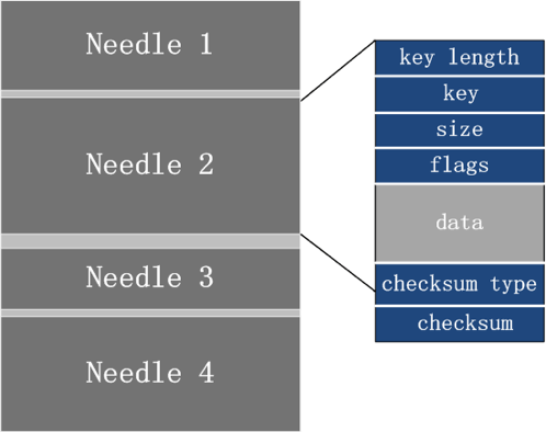
Haystack的数据文件部分

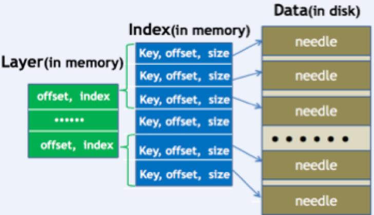
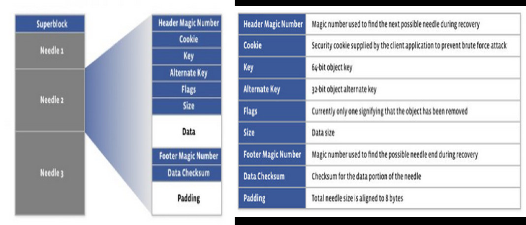
Haystack的数据文件,将每个小文件封装成一个needle,包含文件的key、size、data等数据信息。所有小文件按写入的先后顺序追加到数据文件中。

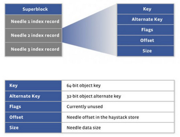
Haystack的索引文件部分

Haystack的索引文件保存每个needle的key,以及该needle在数据文件中的offset、size等信息。程序启动时会将索引加载到内存中,在内存中通过查找索引,来定位在数据文件中的偏移量和大小。

Haystack面临的问题

Facebook的Haystack特点是将文件的完整key都加载到内存中,进行文件定位。机器内存足够大的情况下,Facebook完整的8字节key可以全部加载到内存中。

但是现实环境下有两个主要问题:

  1. 存储服务器内存不会太大,一般为32G至64G;
  2. 小文件对应的key大小难控制,一般选择文件内容的MD5或SHA1作为该文件的key。

场景举例

  • 一台存储服务器有12块4T磁盘,内存为32GB左右。
  • 服务器上现需存储大小约为4K的头像、缩略图等文件,约为10亿个。
  • 文件的key使用MD5,加上offset和size字段,平均一个小文件对应的索引信息占用28字节。
  • 在这种情况下,索引占用内存接近30GB,磁盘仅占用4TB。内存消耗近100%,磁盘消耗只有8%。

所以索引优化是一个必须要解决的问题。

Haystack_plus

Haystack_plus的核心也由数据文件和索引文件组成。

1. Haystack_plus的数据文件

与Facebook的Haystack类似,Haystack_plus将多个小文件写入到一个数据文件中,每个needle保存key、size、data等信息。

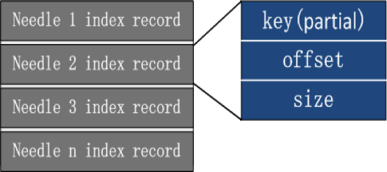
2. Haystack_plus的索引文件

索引是我们主要优化的方向:

  • 索引文件只保存key的前四字节,而非完整的key;
  • 索引文件中的offset和size字段,通过512字节对齐,节省1个字节;并根据整个Haystack_plus数据文件实际大小计算offset和size使用的字节数。

3. Haystack_plus的不同之处

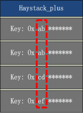
数据文件中的needle按照key的字母顺序存放。

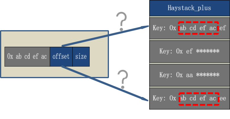
由于索引文件的key,只保存前四字节,如果小文件key的前四字节相同,不顺序存放,就无法找到key的具体位置。可能出现如下情况:

例如:用户读取的文件key是0x ab cd ef ac ee,但由于索引文件中的key只保存前四字节,只能匹配0x ab cd ef ac这个前缀,此时无法定位到具体要读取的offset。

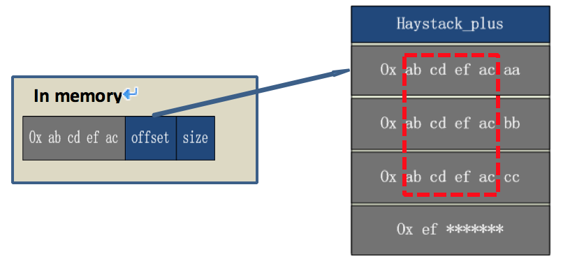
我们可以通过needle顺序存放,来解决这个问题:

例如:用户读取文件的key是0x ab cd ef ac bb,匹配到0x ab cd ef ac这个前缀,此时offset指向0x ab cd ef ac aa这个needle,第一次匹配未命中。

通过存放在needle header中的size,我们可以定位0x ab cd ef ac bb位置,匹配到正确needle,并将数据读取给用户。

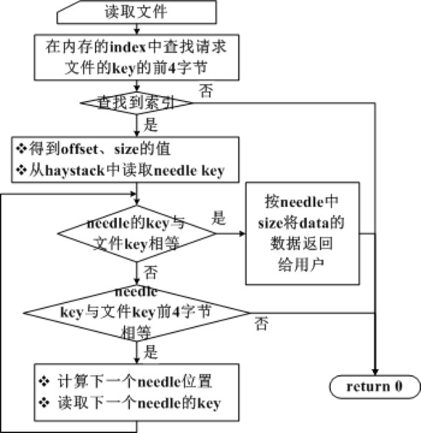
4. 索引搜索流程为

5. 请求不存在的文件

问题:我们应用折半查找算法在内存查找key,时间复杂度为O(log(n)),其中n为needle数目。索引前缀相同时,需要在数据文件中继续查找。此时访问的文件不存在时,容易造成多次IO查找。

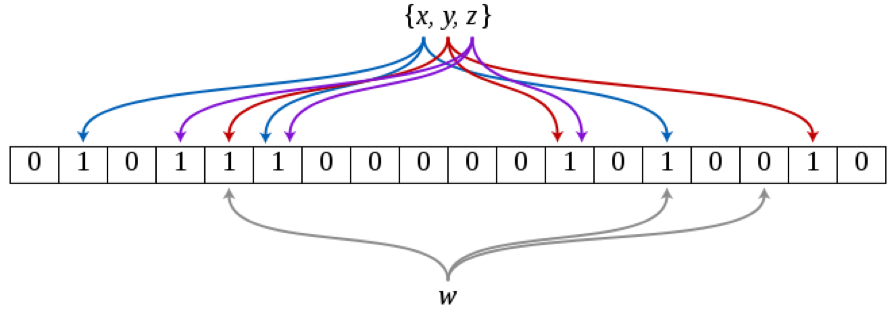
解决方法:在内存中,将存在的文件映射到bloom filter中。此时只需要通过快速搜索,就可以排除不存在的文件。

时间复杂度为O(k),k为一个元素需要的bit位数。当k为9.6时,误报率为1%,如果k再增加4.8,误报率将降低为0.1%。

6. 前缀压缩,效果如何

Haystack_plus与Facebook Haystack内存消耗的对比,场景举例,文件(如:头像、缩略图等)大小4K,key为MD5:

内存消耗对比

Key

offset

size

Haystack

全量key,16字节

8字节

4字节

Haystack_plus

4字节

4字节

1字节

注:Haystack的needle为追加写入,因此offset和size大小固定。Haystack_plus的key使用其前4字节,offset根据Haystack_plus数据文件的地址空间计算字节数,并按512字节对齐;size根据实际文件的大小计算字节数,并按512对齐。

从上图可以看出在文件数量为10亿的情况下,使用Facabook的Haystack消耗的内存超过26G,使用Haystack_plus仅消耗9G多内存,内存使用降低了2/3。

7.索引优化根本就停不下来

10亿个4K小文件,消耗内存超过9G。Key占用4字节,Offset占用4字节,还需要再小一些。

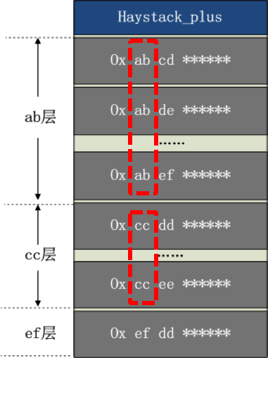
索引分层

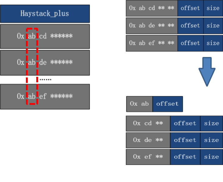
根据文件key的前缀,进行分层,相同的前缀为一层。

分层的好处

减少key的字节数

通过分层,只保存一份重复的前缀,节省key的字节数。

减少offset的字节数

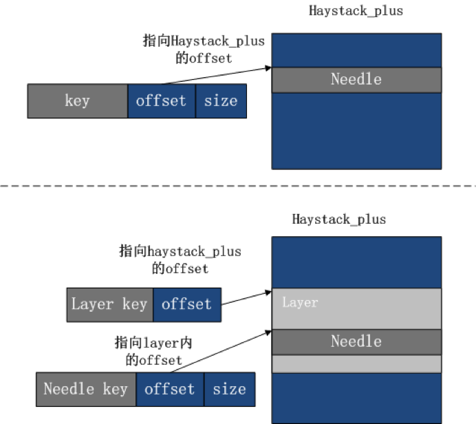
优化前的offset,偏移范围为整个Haystack_plus的数据文件的地址空间。

优化后,只需在数据文件中的层内进行偏移,根据最大的层地址空间可以计算所需字节数。

分层后的效果

从上图可以看出,进行分层后,内存消耗从优化前的9G多,降低到4G多,节省了一半的内存消耗。

Haystack_plus整体架构

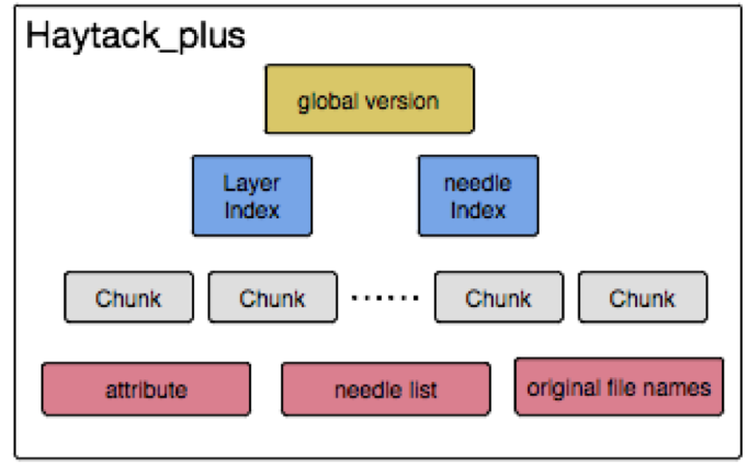
1. Haystack_plus组织

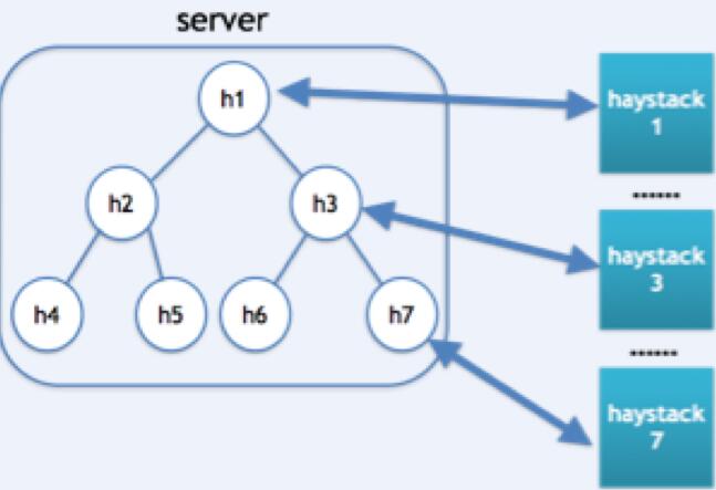
每台服务器上,我们将所有文件分成多个group,每个group创建一个Haystack_plus。系统对所有的Haystack_plus进行统一管理。

读、写、删除等操作,都会在系统中定位操作某个Haystack_plus,然后通过索引定位具体的needle,进行操作。

2. 索引组织

之前已经介绍过,所有needle顺序存放,索引做前缀压缩,并分层。

3. 文件组成

  • chunk文件:小文件的实际数据被拆分保存在固定数量的chunk数据文件中,默认为12个数据块;
  • needle list文件:保存每个needle的信息(如文件名、offset等);
  • needle index和layer index文件:保存needle list在内存中的索引信息;
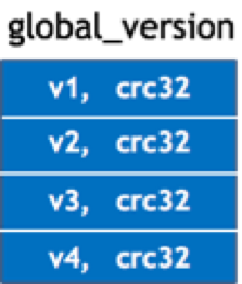
  • global version文件:保存版本信息,创建新version时自动将新版本信息追加到该文件中;
  • attribute文件:保存系统的属性信息(如chunk的SHA1等);
  • original filenames:保存所有文件原始文件名。

A、Haystack_plus数据文件被拆分为多个chunk组织,chunk1,chunk2,chunk3……

B、分成多个chunk的好处:

1. 数据损坏时,不影响其它chunk的数据;

2. 数据恢复时,只需恢复损坏的chunk。

C、每个chunk的SHA1值存放在attribute文件中。

4. 版本控制

由于needle在数据文件中按key有序存放,为不影响其顺序,新上传的文件无法加入Haystack_plus,而是首先被保存到hash目录下,再通过定期自动合并方式,将新文件加入到Haystack_plus中。

合并时将从needle_list文件中读取所有needle信息,将删除的needle剔除,并加入新上传的文件,同时重新排序,生成chunk数据文件、索引文件等。

重新合并时将生成一个新版本Haystack_plus。版本名称是所有用户的文件名排序的SHA1值的前4字节。

每半个月系统自动进行一次hash目录检查,查看是否有新文件,并计算下所有文件名集合的SHA1,查看与当前版本号是否相同,不同时说明有新文件上传,系统将重新合并生成新的数据文件。

同时,系统允许在hash目录下超过指定的文件数时,再重新创建新版本,从而减少重新合并次数。

版本的控制记录在global_version文件中,每次创建一个新版本,版本号和对应的crc32将追加到global_version文件(crc32用于查看版本号是否损坏)。

每次生成新版本时,自动通知程序重新载入索引文件、attribute文件等。

5. 数据恢复

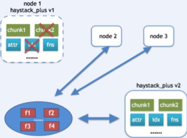
用户的文件将保存成三副本存放,因此Haystack_plus也会存放在3台不同的机器上。

恢复场景一

当一个Haystack_plus的文件损坏时,会在副本机器上,查找是否有相同版本的Haystack_plus,如果版本相同,说明文件的内容都是一致,此时只需将要恢复的文件从副本机器下载下来,进行替换。

恢复场景二

如果副本机器没有相同版本的Haystack_plus,但存在更高版本,那此时可以将该版本的整个Haystack_plus从副本机器上拷贝下来,进行替换。

恢复场景三

如果前两种情况都不匹配,那就从另外两台副本机器上,将所有文件都读到本地上的hash目录下,并将未损坏的chunk中保存的文件也提取到hash目录下,用所有文件重新生成新版本的Haystack_plus。

Haystack_plus效果如何

在使用Haystack_plus后一段时间,我们发现小文件的整体性能有显著提高,RPS提升一倍多,机器的IO使用率减少了将近一倍。同时,因为优化了最小存储单元,碎片降低80%。

使用该系统我们可以为用户提供更快速地读写服务,并且节省了集群的资源消耗。

Link: http://www.infoq.com/cn/articles/solution-of-massive-small-files

由于Jenkins的日志文件很快就被写满了系统磁盘空间,导致很多系统故障。查看了一下日志文件,是由于dns解析异常导致的Jenkins日志爆涨。

首先停掉Jenkins服务,清理掉日志文件,日志文件默认路径/var/log/jenkins/jenkins.log。

为了避免类似问题,关掉此类日志文件。

操作如下:

系统管理-> System Log->日志级别(在左边栏)

添加

Name: javax.jmdns

Level: off

点击提交即可关闭此类日志。

形式

#include <sys/ptrace.h>

int ptrace(int request, int pid, int addr, int data);

描述

Ptrace 提供了一种父进程可以控制子进程运行,并可以检查和改变它的核心image。它主要用于实现断点调试。一个被跟踪的进程运行中,直到发生一个信号。则进程被中止,并且通知其父进程。在进程中止的状态下,进程的内存空间可以被读写。父进程还可以使子进程继续执行,并选择是否是否忽略引起中止的信号。

Request参数决定了系统调用的功能:

PTRACE_TRACEME

本进程被其父进程所跟踪。其父进程应该希望跟踪子进程。

PTRACE_PEEKTEXT, PTRACE_PEEKDATA

从内存地址中读取一个字节,内存地址由addr给出。

PTRACE_PEEKUSR

从USER区域中读取一个字节,偏移量为addr。

PTRACE_POKETEXT, PTRACE_POKEDATA

往内存地址中写入一个字节。内存地址由addr给出。

PTRACE_POKEUSR

往USER区域中写入一个字节。偏移量为addr。

PTRACE_SYSCALL, PTRACE_CONT

重新运行。

PTRACE_KILL

杀掉子进程,使它退出。

PTRACE_SINGLESTEP

设置单步执行标志

PTRACE_ATTACH

跟踪指定pid 进程。

PTRACE_DETACH

结束跟踪

Intel386特有:

PTRACE_GETREGS

读取寄存器

PTRACE_SETREGS

设置寄存器

PTRACE_GETFPREGS

读取浮点寄存器

PTRACE_SETFPREGS

设置浮点寄存器

init进程不可以使用此函数

返回值

成功返回0。错误返回-1。errno被设置。

错误

EPERM

特殊进程不可以被跟踪或进程已经被跟踪。

ESRCH

指定的进程不存在

EIO

请求非法

ptrace系统函数。 ptrace提供了一种使父进程得以监视和控制其它进程的方式,它还能够改变子进程中的寄存器和内核映像,因而可以实现断点调试和系统调用的跟踪。使用ptrace,你可以在用户层拦截和修改系统调用(sys call).

功能详细描述

1)   PTRACE_TRACEME

形式:ptrace(PTRACE_TRACEME,0 ,0 ,0)

描述:本进程被其父进程所跟踪。其父进程应该希望跟踪子进程。

2)  PTRACE_PEEKTEXT, PTRACE_PEEKDATA

形式:ptrace(PTRACE_PEEKTEXT, pid, addr, data)

        ptrace(PTRACE_PEEKDATA, pid, addr, data)

描述:从内存地址中读取一个字节,pid表示被跟踪的子进程,内存地址由addr给出,data为用户变量地址用于返回读到的数据。在Linux(i386)中用户代码段与用户数据段重合所以读取代码段和数据段数据处理是一样的。

3)  PTRACE_POKETEXT, PTRACE_POKEDATA

形式:ptrace(PTRACE_POKETEXT, pid, addr, data)

        ptrace(PTRACE_POKEDATA, pid, addr, data)

描述:往内存地址中写入一个字节。pid表示被跟踪的子进程,内存地址由addr给出,data为所要写入的数据。

4)  TRACE_PEEKUSR

形式:ptrace(PTRACE_PEEKUSR, pid, addr, data)

描述:从USER区域中读取一个字节,pid表示被跟踪的子进程,USER区域地址由addr给出,data为用户变量地址用于返回读到的数据。USER结构为core文件的前面一部分,它描述了进程中止时的一些状态,如:寄存器值,代码、数据段大小,代码、数据段开始地址等。在Linux(i386)中通过PTRACE_PEEKUSER和PTRACE_POKEUSR可以访问USER结构的数据有寄存器和调试寄存器。

5)  PTRACE_POKEUSR

形式:ptrace(PTRACE_POKEUSR, pid, addr, data)

描述:往USER区域中写入一个字节,pid表示被跟踪的子进程,USER区域地址由addr给出,data为需写入的数据。

6)   PTRACE_CONT

形式:ptrace(PTRACE_CONT, pid, 0, signal)

描述:继续执行。pid表示被跟踪的子进程,signal为0则忽略引起调试进程中止的信号,若不为0则继续处理信号signal。

7)  PTRACE_SYSCALL

形式:ptrace(PTRACE_SYS, pid, 0, signal)

描述:继续执行。pid表示被跟踪的子进程,signal为0则忽略引起调试进程中止的信号,若不为0则继续处理信号signal。与PTRACE_CONT不同的是进行系统调用跟踪。在被跟踪进程继续运行直到调用系统调用开始或结束时,被跟踪进程被中止,并通知父进程。

8)   PTRACE_KILL

形式:ptrace(PTRACE_KILL,pid)

描述:杀掉子进程,使它退出。pid表示被跟踪的子进程。

9)   PTRACE_SINGLESTEP

形式:ptrace(PTRACE_KILL, pid, 0, signle)

描述:设置单步执行标志,单步执行一条指令。pid表示被跟踪的子进程。signal为0则忽略引起调试进程中止的信号,若不为0则继续处理信号signal。当被跟踪进程单步执行完一个指令后,被跟踪进程被中止,并通知父进程。

10)  PTRACE_ATTACH

形式:ptrace(PTRACE_ATTACH,pid)

描述:跟踪指定pid 进程。pid表示被跟踪进程。被跟踪进程将成为当前进程的子进程,并进入中止状态。

11)  PTRACE_DETACH

形式:ptrace(PTRACE_DETACH,pid)

描述:结束跟踪。 pid表示被跟踪的子进程。结束跟踪后被跟踪进程将继续执行。

12)  PTRACE_GETREGS

形式:ptrace(PTRACE_GETREGS, pid, 0, data)

描述:读取寄存器值,pid表示被跟踪的子进程,data为用户变量地址用于返回读到的数据。此功能将读取所有17个基本寄存器的值。

13)  PTRACE_SETREGS

形式:ptrace(PTRACE_SETREGS, pid, 0, data)

描述:设置寄存器值,pid表示被跟踪的子进程,data为用户数据地址。此功能将设置所有17个基本寄存器的值。

14)  PTRACE_GETFPREGS

形式:ptrace(PTRACE_GETFPREGS, pid, 0, data)

描述:读取浮点寄存器值,pid表示被跟踪的子进程,data为用户变量地址用于返回读到的数据。此功能将读取所有浮点协处理器387的所有寄存器的值。

15)  PTRACE_SETFPREGS

形式:ptrace(PTRACE_SETREGS, pid, 0, data)

描述:设置浮点寄存器值,pid表示被跟踪的子进程,data为用户数据地址。此功能将设置所有浮点协处理器387的所有寄存器的值。


link: http://blog.sina.com.cn/s/blog_4ac74e9a0100n7w1.html

首先从整体上介绍git服务器的工作原理:多个客户端,其中可以包括仓库管理员,通过将自己的ssh公钥上传到服务器仓库keydir目录,统一调用Git专用账号git进行访问git仓库,不同的用户可以根据不同的ssh公钥校验登录,进行项目版本的各种操作,包括clone,commit,push,pull等等。
    下面具体介绍Git服务器的搭建,机器环境:ubuntu12.04,Git服务器软件采用gitosis(https://github.com/res0nat0r/gitosis ,网上很多文章给的地址根本无法使用,都是copy的,不给力啊! )。
一、软件安装
    1.1 安装ssh的服务端和客户端:sudo apt-get install openssh-server openssh-client
    1.2 安装git-core软件,这个是git服务的基础:sudo apt-get install git-core
    1.3 安装 Gitosis,这个是git服务器软件

de>sudo apt-get install python-setuptoolsde>de>
de>de>cd /tmp
de>de>git clone https://github.com/res0nat0r/gitosis.git
de>de>
de>de>cd gitosisde>

sudo python setup.py install 


    ok,软件的安装都此结束。
 
二、创建Git专用账号git
    sudo useradd -m -s /bin/bash git    //创建git账号,用户家目录默认为/home/git,shell为/bin/bash
    sudo passwd git    //设置git用户的密码
 
三、初始化Git仓库
    1、初始化Git仓库需要一个管理员账号,如上图所示,管理员也是一个客户端用户,所以需要在客户端主机(我的客户端机器是Win7系统)生成一个用户,并且生成ssh-key。具体操作如下:
        
        在客户端安装ssh服务,包括客户端和服务端。如果你的客户端系统是:
            (1)Windows机器,建议直接安装git bash软件,其中包括了ssh这个服务;
            (2)Linux系统,可以按照先前的命令apt-get install openssh-server openssh-client安装ssh服务。
        
        在客户端机器我的账号是huixiao200068,在用户家目录中生成ssh-key:
            (1)Windows机器,打开git bash软件,输入命令
                        cd ~
                        ssh-keygen -t rsa
            (2)Linux系统,也执行以上相同的命令,即可以生成当前用户的ssh-key。
            执行完成之后,输入命令:ls -al,如果出现了.ssh目录,则表示ssh-key成功创建。
    2、把ssh的公钥上传到服务器,我这里假设上传到服务器的临时目录/tmp。
        scp  ~/.ssh/id_rsa.pub git@server:/tmp    //命令中的server改成你自己服务器的IP
    到此为止,仅仅只是做好了初始化仓库的准备工作,上面的2步操作都是在客户端操作的。下面是关键的第三步——初始化,该步骤在服务器端执行。
 
    3、初始化
        sudo -H -u git gitosis-init < /tmp/id_rsa.pub    //将git仓库目录初始化到了git用户家目录下
        此时,git用户的home目录中将出现repositories目录,该目录为git的仓库。
        修改目录权限:sudo chmod 755 /home/git/repositories/gitosis-admin.git/hooks/post-update,该步骤尚不清楚其具体的作用,修改了这个目录的权限有啥用呢?望各位指教。
恭喜你,到此为止,你已经创建了一个git仓库,而且账号huixiao200068是git仓库的管理员啦。下面要做的就是仓库配置啦,管理项目和用户。
四、下载仓库配置项目gitosis-admin到本地客户端
        因为git仓库的配置文件都是以git方式来管理的,所以你需要先下载一份到客户端本地 。
        在你的用户目录下面创建一个临时目录work,
        然后 进入到该目录:cd work,
        然后执行命令:
        git clone git@server:gitosis-admin.git    // 命令中的server改成你自己服务器的IP
        执行完成之后,work目录下会生成gitosis-admin目录,目录下面有一个gitosis.conf文件和一个keydir目录,它们将是下面配置任务的主要操作对象,请牢记它们的位置。
五、新建项目
       1、修改配置文件gitosis.conf,增加如下内容。
            [group first-pro]    //用户组名
            members = huixiao200068    //成员名,多个成员可以用空格隔开
            writable = first-pro    //项目名及其用户对于此项目的权限,目前是可写
        2、创建项目目录 mkdir first-pro
             初始化该目录 cd first-pro;    git init
             添加远程仓库 git remote add origin git@SERVER:first-pro.git
             创建工程文件 touch 1.txt
             添加工程文件到本地仓库中 git add ./1.txt
             提交整个项目到本地仓库 git commit -m “comment”
             提交整个项目到远程仓库 git push origin master    //只有这样子,团队其他开发人员才能看到你修改的代码
             查看提交日志 git log
             查看本地库当前的状态,比如是否有文件需要提交。 git status
        新的项目仓库已经生成,其他开发人员可以git clone 命令从服务器上下载一份工程到自己的本地机器上,协同开发啦!
 
六、新建用户

        关于上一节最后提到的内容,“其他开发人员”,他们是需要管理员来增加和配置的,这一节主要讲怎么添加用户。

(1)客户端操作:
        首先要生成ssh-key,方法和上述说明的一样。
        cd ~
        ssh-keygen -t rsa
        然后一直回车,就OK。然后将生成的id_rsa.pub文件传给GIT服务器管理员
 
(2)服务器端操作:
        管理员将客户上传的id_rsa.pub文件移到gitosis-admin/keydir目录中,并且改名为CLIENT_NAME.pub。注意:如果客户端如下图所示
        ,则CLIENT_NAME为sean@bogon,否则后续操作会出现“Repository read access denied”的错误。
         给项目first-pro增加新的开发者,编辑gitosis.conf文件,vi gitosis.conf。
          [group first-pro]    //用户组名
          members = huixiao200068 sean@bogon    //成员名,多个成员可以用空格隔开
          writable = first-pro    //项目名及其用户对于此项目的权限,目前是可写
         提交修改的管理文件:
            git commit -a -m “add user sean@bogon”
            git push origin master
完成上述2步之后,即可以使用该账号共同开发项目first-pro啦!
        cd ~
        git clone git@SERVER:first-pro.git    //克隆项目到本地
        ……    //do anything you want to do
        commit -am “comment”
        commit push origin master
link: http://blog.163.com/xiaohui_1123@126/blog/static/398052402012102751349705/

在默认拥有的腾讯云服务器是没有额外的数据盘的,默认Linux只有8GB系统盘,一般的网站也足够使用,如果额外购买的数据盘安装系统之后根据不同的面板、系统的路径问题可能不会自动加载到指定的数据盘目录,需要我们手工进行加载数据盘 ,也就是我们常说的挂载。

第一、检查硬盘设备是否有数据盘

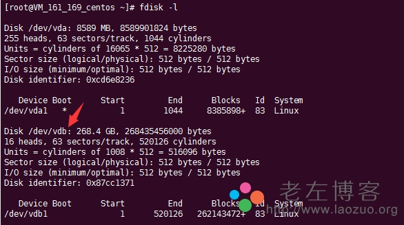
当然,在写这篇文章的时候,我是知道有数据盘的,但有些时候我们购买的VPS,默认比如30GB,可能还有20GB没有挂载,所以也需要类似这样的操作先检查一遍。

fdisk -l

检查腾讯云服务器数据硬盘

我们可以看到有268GB的数据盘没有挂载,看好前面的路径/dev/vdb

第二、数据硬盘分区

fdisk /dev/vdb

依次输入 n 、p、 1、 回车、回车、wq

这里的VDB是我们上面看到数据硬盘的名称,如果你不是这个需要根据你真实的盘名称替换,如果是和我一样,那就直接复制。

第三、ext3格式化分区

mkfs.ext3 /dev/vdb1

第四、挂载新分区

A – 新建目录

mkdir /home

因为AMH面板是安装在HOME目录的,所以我们需要新建目录,如果是WDCP面板,我们应该知道是WWW目录。

B – 挂载分区

mount /dev/vdb1 /home

第五、写入fstab 设置开机自动挂载

echo ‘/dev/vdb1 /home ext3 defaults 0 0’ >> /etc/fstab

第六、检查是否挂载成功(df -h )

这里我们可以看到247GB(250GB)已经挂载完成,在HOME目录中。


link: http://www.laozuo.org/4888.html